In the mid-1960s, radar level gauges began to be produced and used abroad. It is a non-contact liquid level measuring instrument that adopts microwave measurement technology and is mainly used for liquid level measurement in marine oil tanks, overcoming many disadvantages of using mechanical contact-type liquid level instruments. Subsequently, radar level gauges were used for liquid level measurement in onshore storage tanks and in refining units. With the development of the petrochemical industry, its application scope has become increasingly wide, especially its relatively high accuracy meeting the requirements of material measurement.
Radar level gauges have two working modes: pulsed microwave mode (PTOF) and frequency-modulated continuous wave mode (FMCW), corresponding to different measurement principles respectively. PTOF is a "top-down" time-of-flight measurement system that emits microwave pulses of a fixed frequency through the antenna, and the measurement system calculates the liquid level based on the reflected microwave pulses; FMCW transmits a continuous wave with a linearly modulated frequency through the antenna and calculates the liquid level height based on the frequency difference between the transmitted wave and the reflected wave.
During the development process, radar level gauges have been continuously improved and perfected. For example, more advanced technologies are adopted to improve measurement accuracy, additional functions are added to meet different application requirements, and costs are reduced through optimized design. Meanwhile, with the development of industrial automation and intelligence, radar level gauges have gradually been integrated with other systems to achieve more efficient production and management.
In recent years, radar level gauges have been widely applied globally. In industries such as chemical, petroleum, pharmaceutical, and food, radar level gauges are used for liquid level measurement in equipment such as storage tanks, reactors, and pipelines to ensure the safety and stability of the production process. Besides, in fields such as water conservancy, environmental protection, and municipal administration, radar level gauges are also used for monitoring and controlling water levels and liquid levels.
Our Fuzhou CHINASIMBA Electronics Co., Ltd. (CHINASIMBA), established in 2004, is the developer and publisher of the world's first terahertz 120GHz radar level meter. In the past 20 years, we have remained true to our original intention and focused on designing and manufacturing industrial automation products.
CHINASIMBA is a cultivator of radar level measurement technology in China. It constantly introduces new ideas and innovations in measurement technology fields such as pulsed radar, Doppler radar, FMCW frequency-modulated wave radar, 120GHz terahertz 3D level scanner, metrology-grade magnetostrictive liquid level gauge, etc., providing technical support for solving application problems for industrial-level customers all over the world. Over the past two decades, we have provided radar OEM products for 30 industrial enterprises and various civil radar products for 150 customers worldwide.
The working principle of millimeter-wave radar for liquid level measurement is based on the emission and reception of high-frequency electromagnetic waves and advanced signal processing technology. The radar system first emits millimeter-wave signals to the liquid surface to be measured through the transmitting antenna. These signals will be reflected when encountering the liquid surface. The reflected electromagnetic wave signals are captured by the receiving antenna and converted into electrical signals for processing. The signal processing unit will amplify, filter, and demodulate the received signals to eliminate noise and interference and improve the signal-to-noise ratio of the signals. By analyzing the flight time of the signal and combining the propagation speed of electromagnetic waves in the air, the distance between the radar antenna and the liquid surface can be accurately calculated, thereby obtaining the height of the liquid level. This non-contact measurement method not only has high precision and high sensitivity but also has the advantages of no wear, no maintenance, and is suitable for liquid level monitoring in various complex environments.
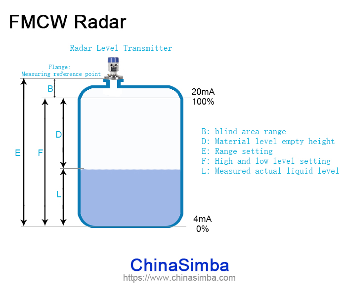
Figure 1
B - Measurement blind zone; E - Measurement range setting; F - Full tank height (high and low level setting); D - Distance from the probe to the surface of the medium; L - Actual measured liquid level. The running time of the radar signal from emission to reception is directly proportional to the distance D from the antenna to the surface of the medium, that is: D = v * t / 2. In the formula, t is the time interval from the emission to the reception of the pulse, and v is the wave propagation speed. As the empty tank distance E is known, the actual material level distance L can be calculated as: L = F - D. In the formula, F is the actual measurement working range.
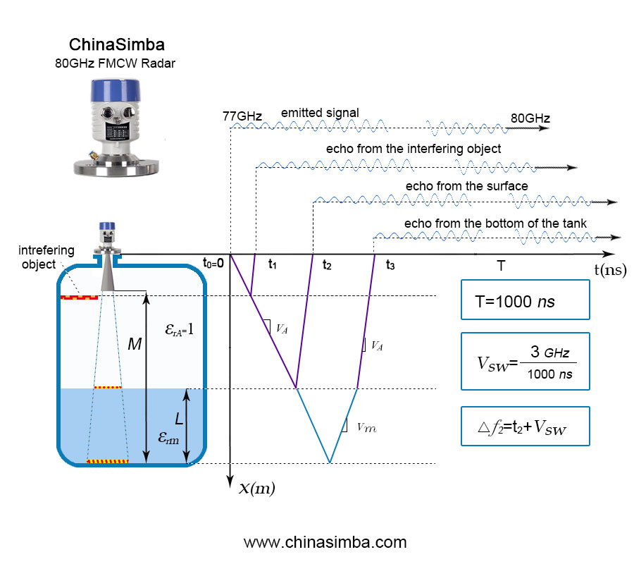
Figure 2
FMCW (Frequency Modulated Continuous Wave) is a technique that uses high-frequency continuous waves with frequency varying in a triangular wave pattern over time. FMCW technology and pulsed radar technology are two techniques used in high-precision radar ranging. The basic principle is that the transmitted wave is a high-frequency continuous wave, and its frequency changes according to the triangular wave pattern over time. The frequency of the echo received by the radar is the same as the transmission frequency change pattern, both following a triangular wave pattern, but with a slight time difference. This tiny time difference can be used to calculate the target distance.
The name FMCW(Frequency Modulated Continuous Wave) fully explains the working principle. Starting from t0 as the initial time, the transmitter circuit increases the radiated frequency in a linear manner over time. (The amplitude of the signal is constant, and after time T, the radiation is periodically repeated). In the example shown in Figure 2, the frequency varies between 77GHz and 80GHz. Most of the signal is reflected by the surface, some by interfering objects, and finally reflected back from the bottom of the tank, with time delays of t1, t2, and t3, respectively. These delays are not measured directly by the system. The amplitude of the received signal is proportional to the degree of reflection; its frequency varies between 77GHz and 80GHz and remains constant. The transmitted and received signals coexist in the antenna. To make precise measurements, it is necessary for the transmitted frequency to change linearly over time. The principle of signal processing is shown in Figure 3, where a mixer is used to combine the transmitted and received signals, producing a signal containing the sum and difference frequencies of the incoming signal. A low-pass filter only allows the very low-frequency differential frequency to pass. The spectrum of the differential frequency provides the echo signal itself, as the frequency is proportional to the delay time (travel times), while the amplitude is proportional to the strength of the echo signal.

Figure 3
Overview of Radar Level Gauge Characteristics
Radar level gauge, as an outstanding measurement device in complex industrial environments, has won the favor of many industry users with its excellent performance and wide applicability. Here are several notable characteristics of radar level gauges:
(1) Continuously stable and high-precision measurement
Based on the electromagnetic wave principle, radar level gauge performs non-contact measurement, and its measurement process is hardly affected by external environmental interference. Therefore, it can provide accurate and rapid measurement results regardless of the medium, including toxic, corrosive media, or solid, liquid, dusty, and slurry media. At the same time, the probe exhibits high stability to changes in temperature, pressure, and gas, ensuring the reliability of measurement accuracy even under extreme conditions such as 450°C high temperature or 50bar high pressure.
(2) Excellent interference suppression capability
In complex industrial environments, factors such as joints, feeding or discharging noise within the beam range may interfere with measurement results. However, radar level gauges are equipped with advanced fuzzy logic control functions that can effectively suppress these interfering echoes, ensuring the accuracy and reliability of measurement data.
(3) High precision, safety, and environmental friendliness
Radar level gauges provide accurate and safe measurements under vacuum or pressurized conditions, meeting the needs of various working environments. At the same time, their materials have excellent chemical and mechanical stability, not only high reliability but also environmentally friendly, with materials that can be recycled to reduce the impact on the environment.
(4) Exceptional durability and reliability
Radar level gauges utilize microwave technology, which is not affected by external interference and does not directly contact the measured medium. Therefore, it is suitable for almost all types of measurement occasions, such as vacuum measurement, liquid level measurement, or material level measurement. The use of advanced materials enables it to operate stably for a long time under complex chemical and physical conditions, providing users with accurate and reliable analog or digital material level signals.
(5) Easy maintenance and operation
To facilitate user use and maintenance, radar level gauges are equipped with fault alarm and self-diagnosis functions. When the equipment malfunctions, the operation display module will provide an error code, and users can easily analyze and troubleshoot the fault based on the error code. In addition, the maintenance and calibration processes have been greatly simplified, reducing users' maintenance costs and time.
(6) Wide application range
Radar level gauges can measure almost all types of media, regardless of the media type, container shape, or working environment. Whether it is a spherical tank, horizontal tank, cylindrical tank, or cylindrical cone tank; whether it is a storage tank, buffer tank, microwave tube, or bypass pipe; whether it is liquid, particles, or slurry, radar level gauges can provide accurate liquid level measurement data. This wide applicability makes it a leader in the field of industrial measurement.
Installation of Radar Level Gauge
The accurate measurement of a radar level gauge relies on the reflected signal of the electromagnetic wave. If the liquid surface cannot reflect the electromagnetic wave back to the radar antenna or if there are interfering objects within the signal range that reflect interfering waves to the radar level gauge at the selected installation location, the radar level gauge will not accurately reflect the actual liquid level. Therefore, choosing an appropriate installation location for the radar level gauge is crucial, and the following points should be noted during installation:
(1) The axis of the radar level gauge antenna should be perpendicular to the reflecting surface of the liquid level.
(2) Objects such as stirring valves, adhering substances on the tank wall, and steps within the signal range of the radar level gauge can produce interfering reflected waves that affect the liquid level measurement. It is necessary to select an appropriate installation position during installation to avoid interference from these factors.
(3) For horn-type radar level gauges, the horn mouth should extend beyond the inner surface of the installation hole by a certain distance (>10mm). The antenna of the rod-type liquid level gauge should protrude from the installation hole, and the length of the installation hole should not exceed 100mm. For circular or elliptical containers, it should be installed at a distance of 1/2R (R is the radius of the container) from the center. It should not be installed at the center of the top of the circular or elliptical container, otherwise, the radar waves will be reflected multiple times on the container wall and converge at the center of the container top, forming a strong interfering wave that will affect accurate measurement.
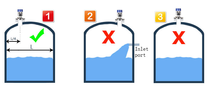
Figure 4
◆ It is recommended that the distance from the inner wall of the tank to the outer wall of the installation tube should be less than or equal to L/4 of the tank diameter.
◆ The best installation position is ①, with a minimum distance of 300mm from the tank wall, and a recommended installation distance >= 500mm.
◆ It should not be installed above the feed inlet ②.
◆ It should not be installed at the center position ③. If installed at the center, multiple false echoes will be generated, causing interference and leading to signal loss.
◆ If the distance between the instrument and the tank wall cannot be maintained, the medium adhering to the tank wall will cause false echo storage.