ANL-9107 24GHz FMCW radar level Gauges Overview
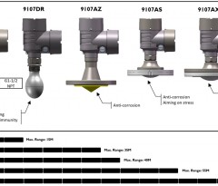
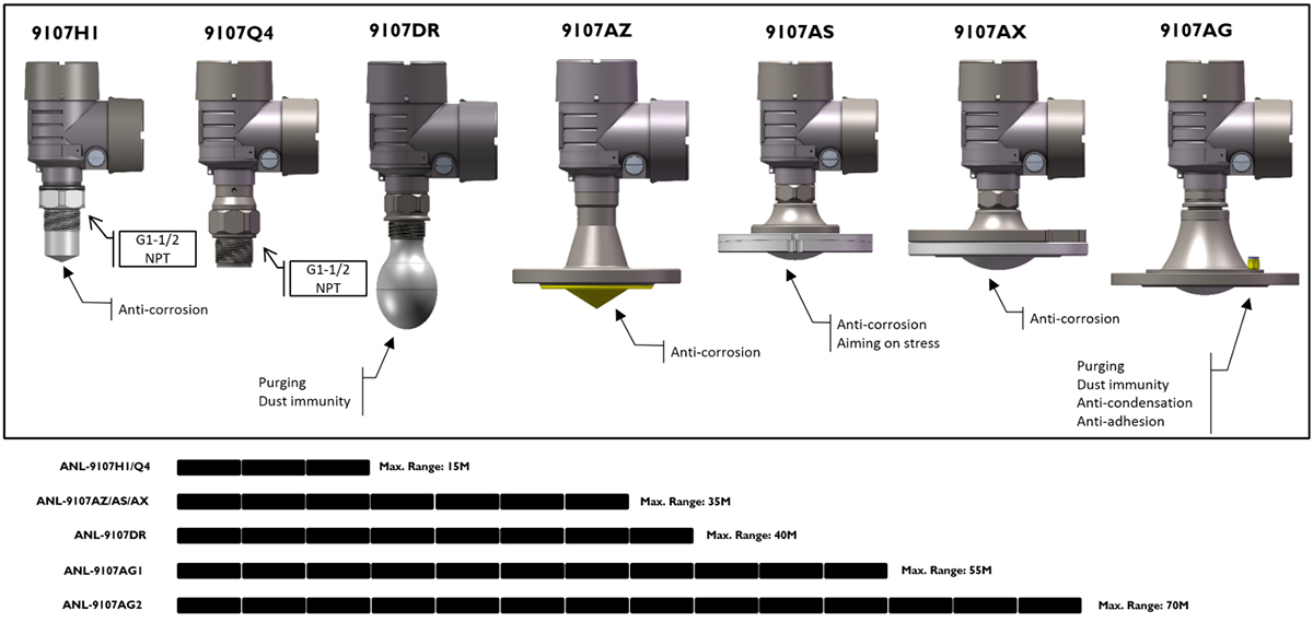
The ANL9107 series represents a range of 24GHz FMCW (Frequency Modulated Continuous Wave) technology-based radar level transmitters designed for high-precision level measurement. Comprising various models such as H1, Q4, DR, AZ, AX, AS, AG, each model is optimized for specific application environments. The ANL9107 series boasts remarkable measurement stability and high accuracy, making it suitable for liquid and solid material level measurements across various industries.
Key Features:
- High Measurement Accuracy: Leveraging FMCW radar technology, it achieves measurement accuracy up to ±2mm.
- Wide Temperature Range: Supports process temperature measurements from -40°C to +180°C (select models support higher temperatures).
- Multiple Materials and Protection Ratings: Housings are available in plastic, stainless steel, or aluminum, with protection ratings up to IP68, ideal for harsh industrial environments.
- Wireless Communication: Bluetooth 5.0 capability facilitates easy field commissioning and maintenance.
- Diverse Signal Outputs: Offers a range of communication protocols including 4-20mA, HART, Modbus, Profibus, among others.
Applications:
- Level measurement in small reactors, storage tanks, and other vessels in the chemical industry.
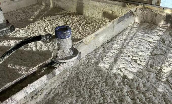
- Material level monitoring for solids such as granules and powders.
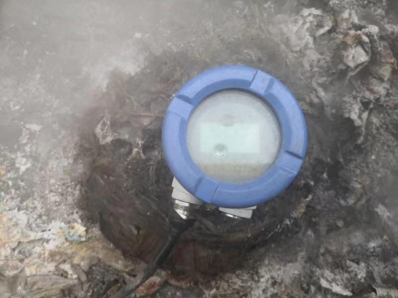
- Level measurement in high-temperature, high-pressure, and corrosive conditions.
- Suitable for complex media scenarios including foams, vapors, and dusty environments.
| Document Download |
ANL-9107 24GHz FMCW radar level Gauges Overview
Housing Versions
The housings are available as single chamber or double chamber version in plastic, stainless steel or aluminum. They are available with protection ratings up to IP 68, and the process seal is made of FKM, FFKM or graphite. For instruments with double chamber housing two supplementary electronics such as radio module or a power pack are available. You will find a complete overview of the available drawing in the Available enclosures: Housing Drawing.
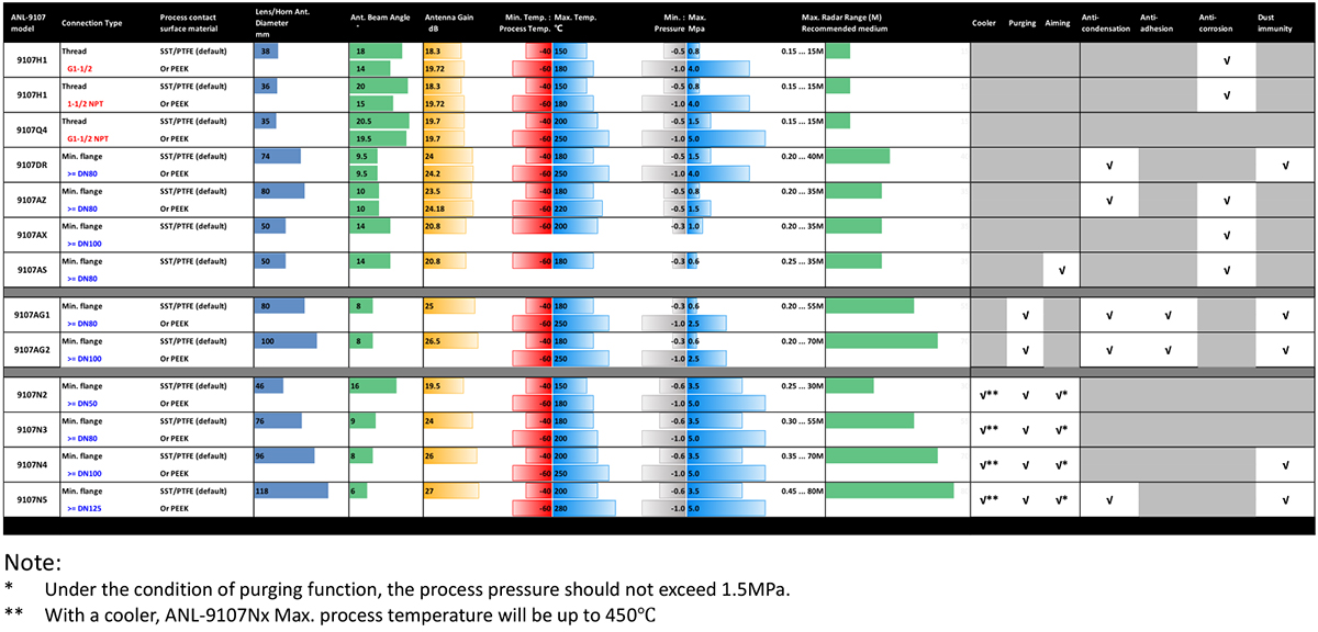
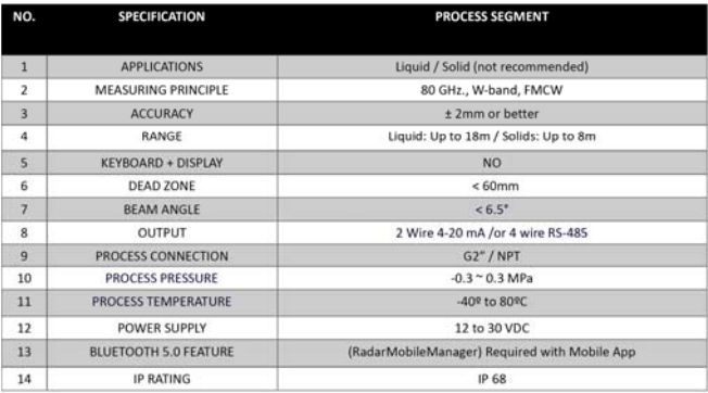
Summary of the ANL-9107 model parameter table (Click to see larger image)

- Details
- Parent Category: Services
- Category: Technology Share


- Details
- Parent Category: Services
- Category: Technology Share
ANL/AiW-4120 series 120GHz FMCW radar level Gauges Overview
The ANL/AiW-4120MP/MC/MP/MG/GX series of intelligent radar level transmitters provide accurate continuous level measurement in a wide range of process applications. Its versatile design enables fit-for-purpose solutions and flexibility of use, especially in the chemical industry and wastewater treatment and green energy applications. For example, ANL-4120 transmitters can be used in tanks/vessels with small process fittings, corrosive environments, and open-air installations. It is certified for use in hazardous locations and complies with NAMUR recommendations.
And for solar- or battery-powered applications, the AiW-4120MB series is recommended. This model supports fast output measuring data (< 2s) when the power supply is powered on, instantaneous low power consumption, low voltage, intermittent wake-up operation mode, and support LoRa, IoT communication.
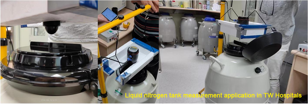
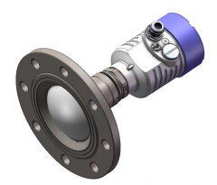
In particular, the ANL-4120MC is ideally suited for Liquid Nitrogen Tank measurement applications, as it does not require an antenna to be mounted inside the LN vessel, but directly outside the vessel, and instead uses the radar electromagnetic wave transmission technology to achieve level measurement, this is already a very successful story.
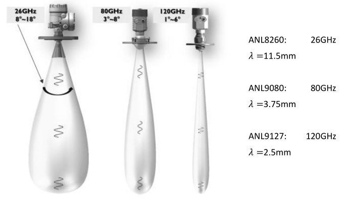
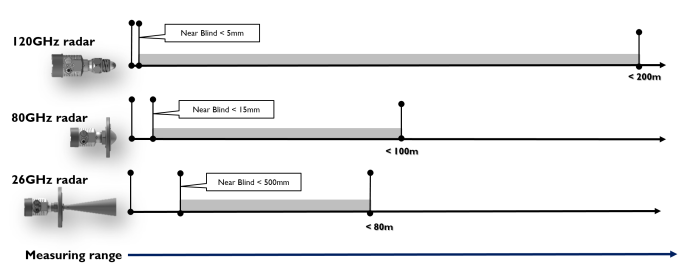
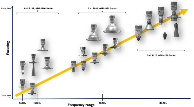
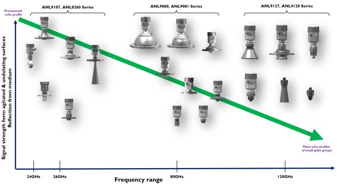
ANL/AiW-4120 model is a product based on FMCW radar technology with 120GHz frequency. Different industrial radar level transmitters have different frequencies, and the frequency can affect the measurement performance. When measuring in the absence (or less) of steam and foam, 120 GHz frequency radar level transmitters are preferred in most normal applications due to greater installation flexibility. However, in some heavy-duty industrial and extreme environments, the ANL/AiW-4120 model is not suitable. We recommend other products for these applications.
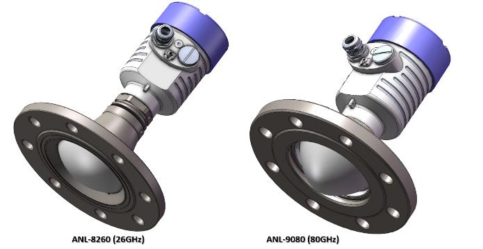
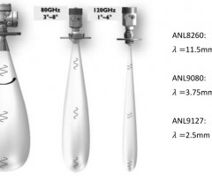
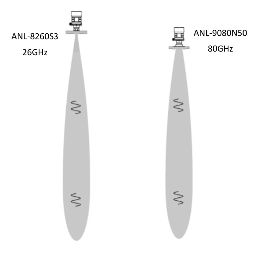
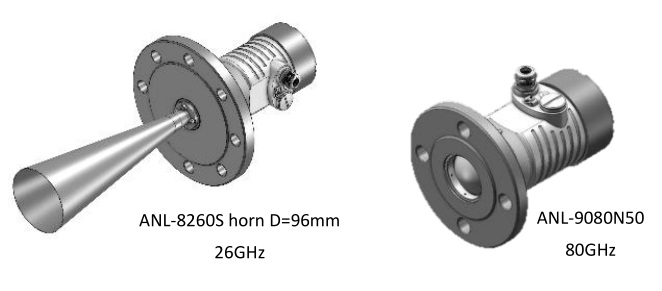
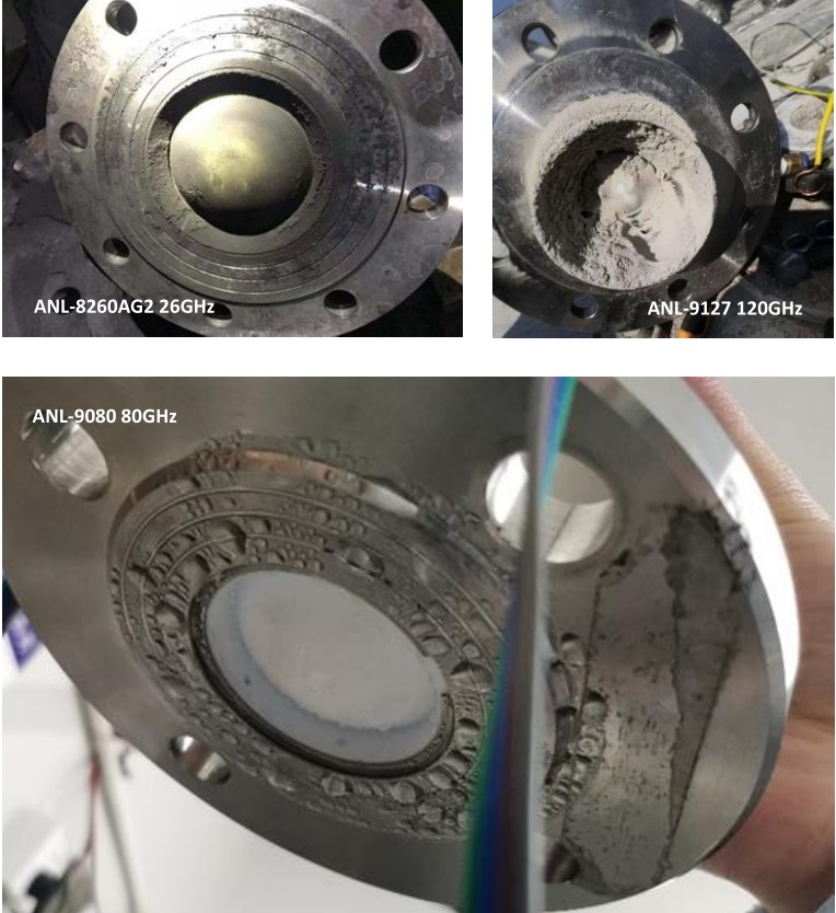
For large-scale smelting, cement, coal power and mining industry applications, we recommend customers to use ANL-9080 or ANL-8260 radar products, which are based on 80GHz and 26GHz radar technology, which are more suitable for process applications in extreme environments, especially solids measuring applications under high dust and pollution conditions.

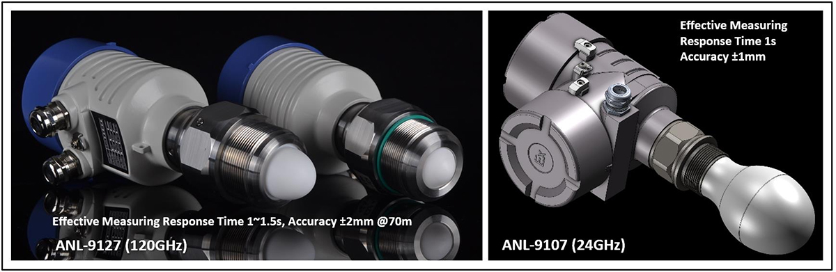
For applications such as sea surface detection or material height measurement on conveyor belts, we recommend ANL-9127 or ANL-8341 products, which are radar level transmitters for high-speed measurements, suitable for measurement applications that require a response time in < 1s.
If the application of high-precision and high-speed measurement is high-precision, it is recommended to use the ANL-9107 high-speed and high-precision version of the radar level transmitter product, which is based on 24GHz FM radar technology.
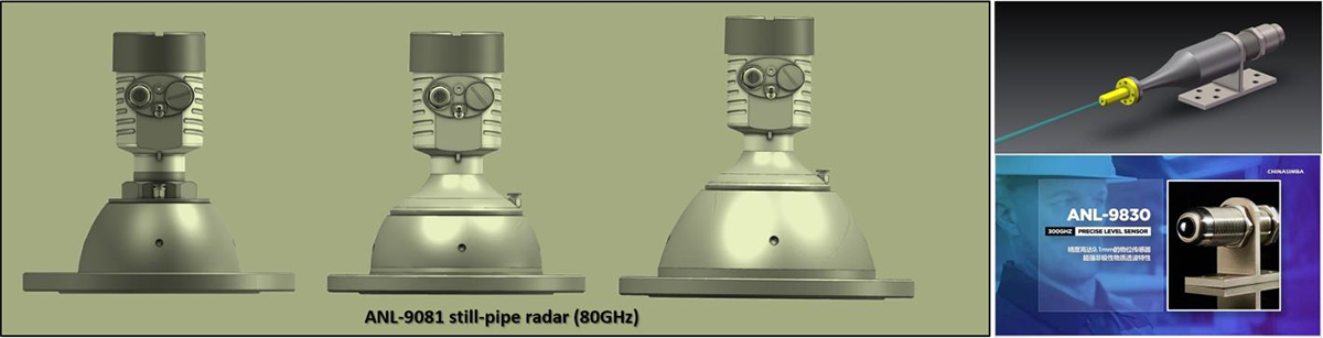
And for the crude oil custody transfer or still pipe measuring with floating roofs and gasoline/product tanks with or without inner floating roofs application, it is recommended to use the ANL-9081 high-precision NC-radar model (80GHz radar technology) or ANL-9830 Extremely high-precision NC-radar model (300GHz radar technology) product.
Note. For more product information, please contact CHINASIMBA sales manager.
(Product manual download:![]() AiW-4120MPMC_120GHz Operation_Manual_DY0723)
AiW-4120MPMC_120GHz Operation_Manual_DY0723)
- Details
- Parent Category: Services
- Category: Technology Share


- Details
- Parent Category: Services
- Category: Technology Share
HOW & WHY to choose AiW-3648 for water treatment applications
HOW & WHY to choose AiW-3648 for water treatment applications
Hight Cost-effective’s AiW-3648. What are its intrinsic factors?
Overview
When we focus on natural water resources, wastewater treatment, and municipal utility management applications, we should pay more attention to the natural environmental temperature adaptability of products, UV resistance, altitude and protection against pollution in the daily life environment.
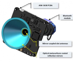
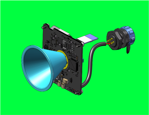
■ AiW-3648’s Antenna Design
The AiW-3648 radar level gauge, it does not adopt the traditional lens antenna design ideas, nor does it have a complex sealing and assembly structure design, which these original designs are designed to overcome the extreme and demanding environments of industrial process applications (process temp. & pressure).
AiW-3648's antenna uses a slit-in-the-top mirror radiation technology, which obsoletes the traditional lens antenna design that is expensive in terms of cost and materials. The overall construction cost of the antenna is only 0.25USD. And It is also built inside the housing and does not need to be exposed (the housing material is PVDF, which has excellent UV and anti-aging properties).
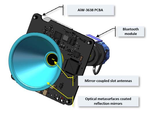
The performance of this antenna is sufficient for the measurement of liquid/solid levels in the range of 20M.
The Beam Angle is 7˚ and the Gain is 18dB.

■Electronic circuit integration
The electronic part of the AiW-3648 is designed with a highly integrated signal processing chip, which makes the hardware circuitry simple and reliable, while also greatly reducing the cost of the product. With just one circuit board, it fulfills all the necessary functions and performance requirements: reverse polarity protection, surge protection, overvoltage protection, current limiting and lightning protection.
■ Summary of the effects of radar frequency AiW-3648 Technical Datasheet
For more further discussions and exchanges are welcome.
This email address is being protected from spambots. You need JavaScript enabled to view it.
https://www.chinasimba.com
- Details
- Parent Category: Services
- Category: Technology Share


- Details
- Parent Category: Services
- Category: Technology Share


- Details
- Parent Category: Services
- Category: Technology Share
- Details
- Parent Category: Services
- Category: Technology Share
