Overview
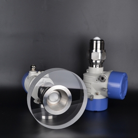
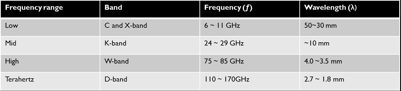
With over 40+ years of continuous development, radar level transmitters have become the preferred technology for level measurement in many of today's industrial applications. For non-contacting radars level transmitters, the microwave frequency transmitted by the radar is one area in which there have been recent developments. Normally, four different frequency bands have been used for level measurement: The C-band (~6 GHz), the X-band (~10 GHz), the K-band (~26 GHz) and the W-band(~80GHz). These frequency bands combine many attractive properties for accurate and reliable millimeter-precision measurement. Recently, radars using 120 GHz frequencies (the lower part of the D-band) have been introduced as a further option. The use of 120GHz radars is mainly driven by the development of 3D radar applications, high-precision measurement and penetration measurement of non-polar materials.
![]()
Frequency is a fundamental property of any radar as it has direct effects on measurement performance. It is important to remember that different frequencies are not equally suitable for all applications. Indeed, radars using different frequencies are required to solve different problems.
This paper will first describe the fundamental physical properties of different frequencies and thereafter explain what practical effects these properties have in some common, real-life level measurement applications. To this end, this paper differentiates between non-contacting radar transmitters using low microwave frequency (6/10GHz), mid frequency (26GHz), high frequency (80GHz) and terahertz frequency(120GHz).
Frequency and wavelength impact
At the fundamental level, radar level transmitter instruments emit microwaves to measure distance. Microwaves are commonly defined as electromagnetic radiation with wavelengths (λ) between 300mm and 3mm. The wavelength is inversely proportional to the microwave frequency (ƒ), i.e. shorter wavelength = high frequency. In the case of microwaves λ=300 mm corresponds to ƒ=1GHz and λ=3mm corresponds to ƒ=100 GHz. The properties of low, mid and high frequency level radars are summarized in below. These different physical properties have direct impact on the suitability of each frequency for different level measuring applications and conditions.
First and foremost, high frequency microwave signals suffer more attenuation (i.e. they are absorbed to a higher degree) when propagating through a medium, resulting in weaker signal return. For a simplified analogy, think of when you hear loud music played by your neighbor: low frequency sound (i.e. bass) will travel long distances and be heard clearly even through walls. High frequency sounds (i.e. treble) however are quickly absorbed and do not carry over long distances or through objects. When it comes to level measurement this means that high frequency radars are more likely to have problems with condensation, vapor, foam, build-up on the antenna, and dust. Low and mid frequency signals with wavelengths in the range of 50 mm to 10 mm are less affected by these kinds of challenges and more likely to pass through them unaffected.
Another important effect of the frequency is that it impacts the antenna beam width and beam angle, i.e. how focused the microwave propagation is. The beam angle and beam width are determined by the antenna design in combination with the microwave frequency. High frequency signals can achieve small beam angles with small antennas. Equally, small beam angles can be achieved with low frequency radars, but this requires larger antennas. The benefit of a small beam angle in level measurement is that it can make it easier to avoid hitting installations in the tank.
However, a narrow beam width can also be a disadvantage. For example, if there is an obstruction directly below the radar a narrow beam will be completely blocked, but a radar with a wider beam will be only partially blocked and still able to measure the product level.
A practical limitation established from experience is that the beam angle should if possible, not be smaller than about 3°, unless it is used for the measurement of straight pipes and the liquid level is statically flat, i.e. in oil tanks. A narrower beam makes installation sensitive to misalignment of the antenna. Consider the extreme case: if a radar has a beam like a laser it is almost impossible to align it with the plumb line on a real-life tank. Consequently, the reflected beam will miss the antenna and the signal will be lost.
Finally, waves and ripples on a liquid’s surface are common in industrial applications and may cause problems for radar level measurement. Instead of reflecting back upwards towards the antenna, microwaves hitting a turbulent surface may scatter and disperse. Thus, a lot of the signal strength (as much as 90 percent) can be lost and give the radar problems with obtaining an accurate and reliable level measurement. Microwaves remain unaffected by surface irregularities such as turbulence if the wavelength is larger than the ripple size. For example, the signal return of high frequency radars will be affected and scattered by ripples down to 3.8 mm in size, whereas mid-range frequencies will remain unaffected by turbulence up to 2.5 times as large and be reflected as if from a flat surface.
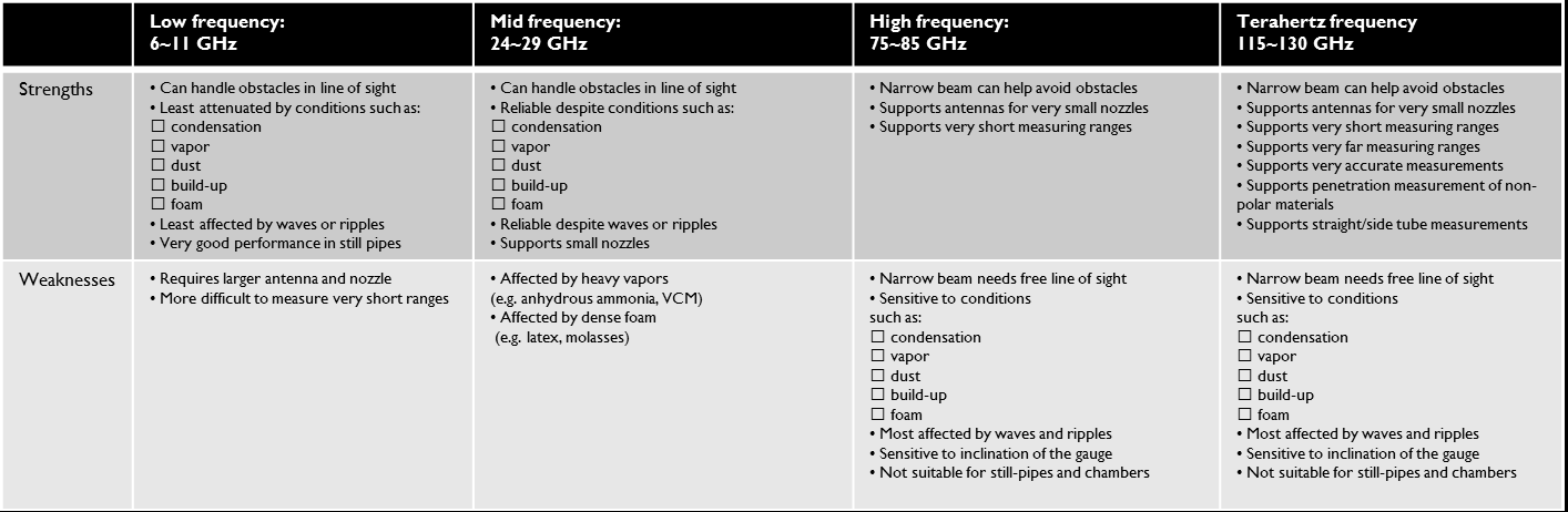
Low, mid, high and terahertz frequencies: strengths and weaknesses
It is clear then that the frequency has a major impact on the type of application a radar is best suited to. The following is a guide to the challenges that exist within some common level measurement applications and the implications of frequency choice.
Application suitability
For dirty and contaminating applications
During operating of a radar level transmitter, dirt and contaminants can build up on the antenna lens over time, which can affect the strength and direction of the radar signal. With radar level gauges operating at low and medium frequencies transceiver, the echo signal is less sensitive to this contamination and can pass through the build-up more or less unaffected. For radar signals operating at high frequencies, more energy is absorbed by the dirt covering the antenna lens, and the direction of the beam may also be shifted. A deposit of uneven thickness covering part of the antenna can redirect the beam by about 1.5°. For radars with narrow beam angles, this can cause serious problems because the return echo is not directed at the antenna, resulting in a loss of signal strength. As a result, low- and medium-frequency technologies are better suited for dirty and polluting applications.
For tanks with condensation and/or vapor applications
Condensation and vapor are sometimes a challenge for radar level measurement. Water reflects microwaves much more strongly than most industrial liquids. Condensation and vapor can therefore cause the reflection from the product surface to be obscured by 'noise' from water droplets. This is more problematic for high frequency signals because their shorter wavelengths also reflect strongly from very small particles like steam and aerosols. Low and mid frequency technology is therefore a better choice for applications with steam and condensation. It should be noted, however, that for condensation the design of the antenna is also of critical importance. Antennas with flat, horizontal surfaces should always be avoided.
Applications with turbulence, waves and ripples
In general, low and mid frequencies perform best in applications with turbulence, waves and ripples. Small ripples on the liquid surface is especially detrimental to high frequency measurements. The short wavelength means that the signal reflection will be scattered also by small surface movements causing loss of returning signal strength. Longer wavelengths are reflected as if from a flat surface and are therefore better suited to this type of application.
Applications with foam
Just like dirt and condensation, a layer of foam on top of the liquid will absorb the radar signal and make accurate measurement more difficult. Foam can have very different properties depending on which product it comes from, but once more, lower frequency generally provides better measurement reliability and accuracy. For dense and thick foam (e.g. from beer, molasses and latex) 6 or 10 GHz works best. For lighter foam, 26 GHz performs very well. High frequency technology should be avoided in applications with foam.
For Bulk liquid storage tanks application
In very large tanks, for example those used for bulk liquid storage at tank terminals, the size and placement of nozzles are typically not a restraint when it comes to choose of radar device. Obstructions and disturbing objects in the tank are usually not an issue either. Due to the vessel size, waves and ripples are often present on the liquid surface. Condensation is also common. As previously explained, this causes problems for high frequency technology.
Many bulk storage tanks are floating roof tanks where measurement is performed through still-pipes. Low frequency radars are preferred as they are less sensitive to build-up on the pipe wall, slots, and pipes that are not completely straight. High frequency radars have difficulties in such situations.
Furthermore, bulk storage tanks often have significant roof movements due to sunlight and shade, wind, and tank bulging. This causes problems for high frequency radars because their narrow beam width makes them very sensitive to tilting, if the axis moves from the vertical plumb line. Tilting can result in the reflected signal 'missing' the antenna opening. It also makes installation of high frequency radars challenging as they must be installed absolutely level in order to perform correctly. Low frequency technology is therefore the most appropriate choice for this kind of application.
For Small to medium size vessels application
This kind of vessel, typically 1~20 m tall, is among the most common in process industry. They are used for a broad range of tasks: from intermediate storage to blending, separation, and as reactor vessels. Process connections are usually 2–4-in. and conditions inside the tank are often difficult with one or several challenges such as condensation, contamination, turbulence, foam, etc. Mid frequency technology is a good choice in this kind of tank due to its versatility – it combines small antennas with good reliability in difficult conditions. Low frequency radars may be less suitable due to the small nozzles and high frequency technology is less able to cope with the tough process conditions.
For Small tanks/buckets
In very small tanks, about 0.5~1.5 m the size and placement of nozzles can be a limitation. The short measuring range and need for small antennas mean that high and mid frequency technology are attractive options for these applications. But of course, previously mentioned challenges such as condensation, contamination, turbulence and foam must be considered where applicable. For Solids For measuring the level of solids, the best frequency to use is very much application dependent. Each technology has its strengths and weaknesses. Low and mid frequencies are able to cope with dust, condensation, and with coarse solids. High frequency works well with very fine powders. Condensation is generally challenging for high frequency radars, but with solids yet another problem arises: condensation in combination with certain solids causes rapid material build up. This will quickly clog small nozzle openings and cover the small antennas of high frequency radars.
Summary
Radar level measurement has come a long way since its introduction 40+ years ago and the technology will continue to develop and improve. The recently introduced radars using the high frequency range may have benefits in level measurement applications for very small tanks with small process connections and very short measuring ranges.
However, the fundamental suitability of 6~11 and 24~29 GHz frequencies for reliable mm-accuracy level measurement cannot be overlooked. High frequency technology will usually perform well in less challenging process conditions, but fundamental microwave physics shows us it is less suitable when the going gets tough.
In contrast, low and mid frequency technology was developed specifically to meet the toughest level measurement challenges in the most demanding industrial applications. And the reason these instruments have been such an incredible success is because they provide reliable and accurate measurements in almost all applications.